


🚀 Elevate your projects with pinpoint GPS precision—because your code deserves the best!
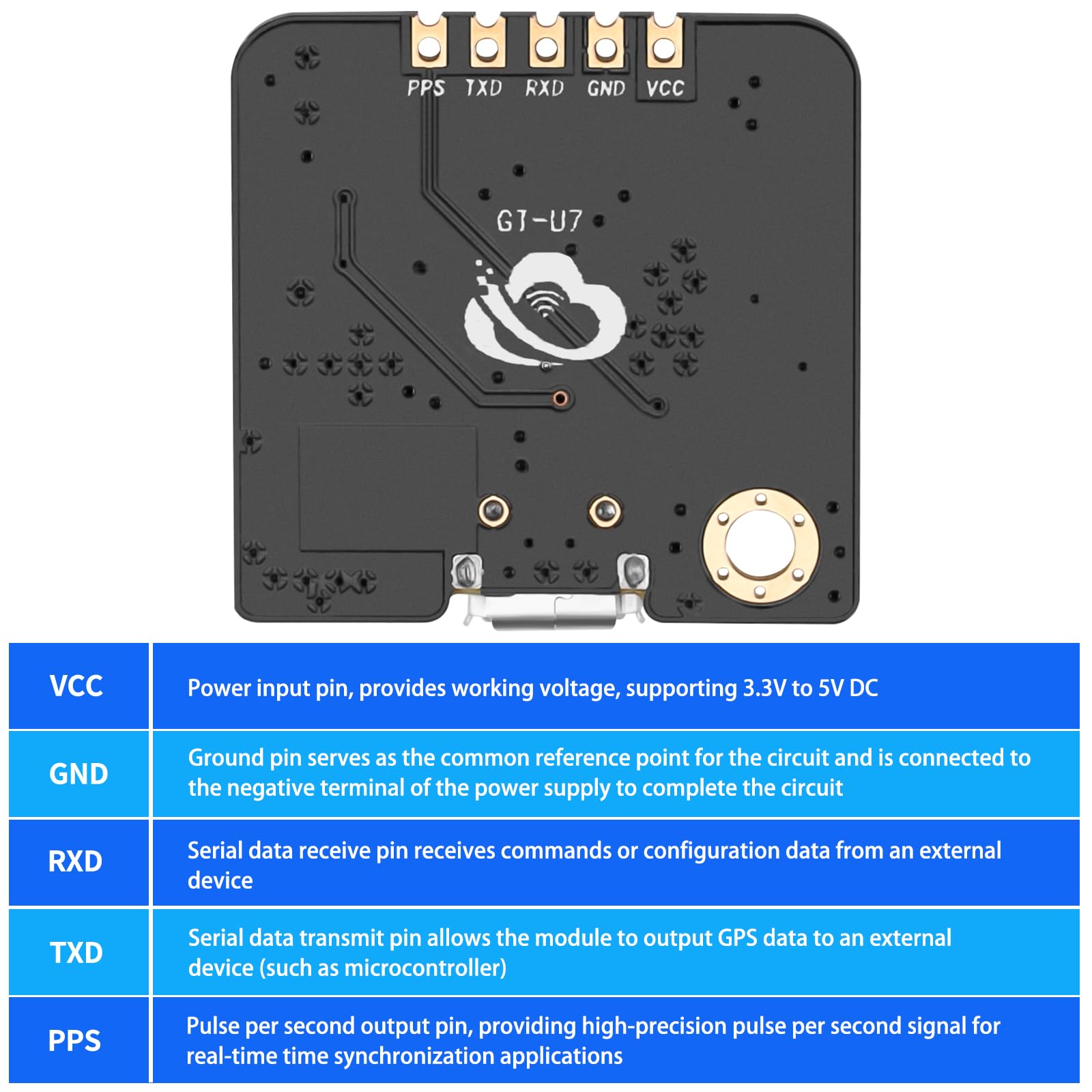
The MakerFocus GT-U7 GPS Module features a 7th generation UBLOX-compatible chip delivering ultra-high sensitivity and low power consumption in a compact form factor. With direct USB connectivity and compatibility with popular microcontrollers like Arduino and Raspberry Pi, it offers seamless integration for precise satellite positioning and advanced timing applications. Ideal for professionals seeking reliable, plug-and-play GPS performance in challenging environments.
| ASIN | B07P8YMVNT |
| Customer Reviews | 4.5 4.5 out of 5 stars (516) |
| Date First Available | February 26, 2019 |
| Item Weight | 0.205 ounces |
| Item model number | SN12SF83QOH11452IC |
| Manufacturer | MakerFocus |
| Product Dimensions | 1.09 x 3.94 x 0.39 inches |
D**N
Excellent for use with a Raspberry Pi. Be careful with an Arduino!
This little unit is a great value. It does appear to use an authentic U-Blox chip under the metal can and white label. Most U-Center software functions seem to work just fine. I interfaced mine to a Raspberry Pi 2 to make an NTP time server. The PPS connection allows accuracy down to a few 10s of nanoseconds. This requires configuring the Raspberry Pi to accept a PPS signal on one of the GPIO pins. I used the "GPSD" and "NTPD" packages, which interface nicely with the unit. Be sure to hook up to the TX and RX serial lines, as GPSD appears to update the time and other parameters that allow a rapid "cold" fix when first powered up. A word on power and levels . The module on the board operates at 3.3v!!!!! However, this board has a 5v > 3.3 volt regulator that allows powering from the USB connector. The Vcc pin also connects to the regulator input. ***UPDATED*** The module can only be powered from 5v on the Vcc pin. The onboard voltage regulator does not function properly with the Vcc pin connected to 3.3v. It appears to function normally, but will be subject to very frequent dropouts of 3D lock and other erratic operation. Also. operating the board from 3.3v on the Vcc pin would subject the device providing power to 5v on its 3.3v output should the USB port be connected to a computer for programming the board. Be careful. The TXD, RXD and PPS pins all operate with 3.3v as their logic high input/output levels!!! A read of the data sheet from the link in the listing clearly states theses interface pins are NOT 5 volt tolerant. That means if you use a device (like an Arduino) that uses 5v as its logic "high" to connect to an input on this device (RXD), you will probably damage the chip. It may work for a while, but it is stressing the chip beyond the absolute maximum ratings. The PPS and TXD pins are outputs, so no damage results connecting these to a device expecting a 5v input, but the data will be very sensitive to noise and corrupted data on the receiving device (an Arduino, for example). It may seem to work OK, but you would do better investing in a cheap bidirectional 5v <> 3.3v level converter chip for a few dollars if you want to connect to an Arduino. The device is perfectly matched in terms of voltage levels to a Raspberry Pi, however!
I**1
Mostly pros. Few cons. Works fine for my application.
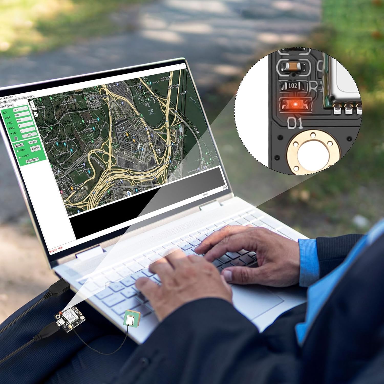
My application is timekeeping, and certainly does not involve flight control. This module was intriguing given its low price relative to other modules. Notes: • MicroUSB connector makes it super quick to check operation against a 9600 baud serial port/terminal. • Operates on 5V, and I’ve confirmed on a scope (and by use) that both the TXD and PPS output TTL levels. • Draws ~35ma @ 5V. • PPS is a positive-going 100ms pulse and it appears that the positive transitions mark the *next* received sentences, and seconds=00. Note that PPSs only appear when there’s an actual fix (eg. $GPRMC Status term = ‘A’) The little red LED on the breakout board seems to be wired as inverse-PPS, so solid red until a fix, then pulsing off in tandem with PPS. Useful. • I confirmed that two otherwise unrelated modules with fixes, do PPS exactly in tandem, as expected. • Sentences output (at 1s intervals of 9600 baud) are ($GP)RMC, VTG, GGA, GSA, GSV & GLL. I only needed RMC & GGA. • Position output was spot-on at least when static on my desk. Had no need to evaluate it in motion. • Sentences seem to work fine with the usual GPS parsing libraries, or if you roll your own. • The breakout module features what appears to be a small rechargeable coin cell spot-welded to its holder, permitting hot-starts. • The supplied patch antenna on a short pigtail with a U.FL connector works well. So does a more substantial GPS antenna terminated with a U.FL. Keep in mind U.FL connectors are not intended for repeated mating cycles. ie, they’re fragile! Use a magnifying glass when connecting. What I find questionable: • Vendors’ Amazon description claims to be “using the original UBLOX (sic) 7th generation chip”. Obviously, the “GT-U7” module on this breakout board does not claim to be a u-blox product. Is it then using some sort of “original” ublox chip inside it? Reading up on how to spot a fake on ublox’s site leads one to believe this is in fact some sort of clone of the u-blox Neo 6 or 7. Startup $GPTXT sentence claims itself as u-blox 7, tho… Questionable if module is in fact configurable via u-center, although u-center has no problem parsing its output. If you are expecting something genuine-ublox, do some research. • Questionable how 5V-tolerant RXD, the sole input on this breakout, might be. Since I do not plan on sending it any configuration, I’m leaving it disconnected and using the module in its default mode. • A schematic of this breakout board would be very useful, in particular to answer the previous question. Can’t seem to find one for it. Aargh. Easy enough to reverse-engineer, given motivation to do so. So, would I trust this product in my 1/8 scale autonomous jet-powered RC A380 model aircraft? Probably not. But for my timekeeping application, it works fine, thus not subtracting any stars since I’m realistic about its pedigree. ---
S**A
Easy way to add GPS to a LORA Meshtastic device
Overall; Recommended. Purchased to add GPS to a Heltec V3 LoRa device running Meshtastic. Hookup instructions can be found on the Meshtastic website and several other locations (Amazon Terms of Use prohibit providing the links, use your fav search engine to find them). Remember to redefine the GPIO pins for RXD (GPS_RX_PIN 45) and TXD (GPS_TX_PIN 46) signals. I didn't bother with the GPS_Enable pin for now, manually disconnecting the VCC header (may add a switch or the switching transistor mod described on the Meshtasitc site later). Pinout on the GPS board is slightly different than the examples I found, but the labeling is correct. I used the headers provided with the Heltec and with the GPS and a set of breadboard jumpers I already had for wiring, this simplifies disconnecting the GPS if not needed. The headers complicate packaging if you want to use one of the case designs on 3D printing sites or available for purchase. Of course, you can solder direct-wire for a less bulky assembly. The antenna is separate and comes with an IPEX connector to attach to the GPS board. The antenna can be mounted to maximize GPS signal reception while the GPS receiver can be mounted for GPS performance is good, and it picks up signals inside my house better than a USB-based GPS I use for 2M VHF AFSK APRS. The additional power consumption is not bad, a few days of tests suggests I can get a bit over 24 hours of operation with a 3000 mAH battery. The Heltec V3 is not ultra low power consumption, so I would expect much longer operation with a less power-hungry LoRa device.
Trustpilot
1 month ago
2 weeks ago