


Buy anything from 5,000+ international stores. One checkout price. No surprise fees. Join 2M+ shoppers on Desertcart.
Desertcart purchases this item on your behalf and handles shipping, customs, and support to Colombia.
🎛️ Elevate your sensor game with precision that commands attention!
The UMLIFE 3pcs AS5600 Magnetic Encoder Sensor Module delivers high-precision 12-bit angle measurement through non-contact magnetic induction. Supporting multiple output modes including I2C, PWM, and voltage, these compact 23x23mm modules are pre-assembled for quick integration into your projects, making them ideal for professional-grade industrial and scientific applications.
| ASIN | B094F8H591 |
| Best Sellers Rank | #31,374 in Industrial & Scientific ( See Top 100 in Industrial & Scientific ) #2 in Switch Encoders |
| Brand | UMLIFE |
| Built-In Media | others |
| CPU Manufacturer | ARM |
| Connectivity Technology | I2C |
| Customer Reviews | 4.4 out of 5 stars 63 Reviews |
| Included Components | others |
| Item Dimensions L x W x H | 0.91"L x 0.91"W x 0.91"H |
| Manufacturer | UMLIFE |
| Mfr Part Number | YY138 |
| Model Name | AS5600 Magnetic Encoder |
| Operating System | Linux |
| Processor Brand | ARM |
| Processor Count | 1 |
| Total Usb Ports | 2 |
| UPC | 701715466333 |
| Warranty Description | 1 |
A**N
Works out of the box using I2C on Arduino!
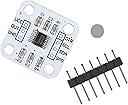
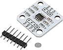
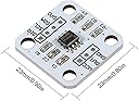
I saw there were some negative reviews or at least comments about it not working with PWM out of the box. Makes sense, and I'm glad one reviewer pointed out how to remove the R4 resistor to make that work. For me, I typically use the AS5600 magnetic encoder using the I2C protocol on Arduino, and so for my application(s) I wasn't interested in PWM. This worked out of the box without any modifications for me, and this ready-to-go board is a huge time saver instead of buying the individual AS5600 chip and soldering the pins to capacitors yourself. Here's how you do it: 1) Connect Vcc to a power supply between 3.3V-3.6V or 4.5-5.5V, e.g. the 5V or 3.3V pin on your Arduino Uno. (if you look online for the AS5600 datasheet, you'll see it supports 3.3-3.6V and 4.5-5.5V, depending on how you connect the capacitors. However, this board has capacitors mounted in such a way that you can go either way! I tested it and it does work with both). 2) Connect GND to the ground of your power supply (or Arduino Uno, for example) 3) Connect the SCL pin to your Arduino's SCL pin, and the SDA pin to your Arduino's SDA pin. These are labeled on the Arduino Uno. On other boards, you'll need to look online for your board's pinout diagram to see which pins are for SCL and SDA. 4) Download a library for the AS5600. A good one is: google "as5600 arduino seeeduino", you'll find a result on the seeedstudio Wiki page for a Grove 12 bit magnetic rotary position sensor (AS5600). On that page is a link to "Download the AS5600 library from github" Download and install that library to your computer, and run the "readAngle" example by opening up your Arduino IDE and clicking File->Examples->Seeed Arduino-Master->readAngle. You should be able to bring a magnet (such as the one included in the package) close to the sensor and using the Serial monitor, you'll see the angle change as you rotate the magnet. Hope this helps anyone else out thee.
D**S
Works Well I2C at 5V
R**N
High accuracy easy to use
Just be aware that the magnet is tiny and very very easy to loose, and if you haven't used magnetic encoders before, know that the magnet needs to be extremely close to the sensor (the black chip), and these magnets are special, you can't just use any.
D**L
Digital outputs fine, analogue don't seem to work
The digital outputs work and you get between 0 and 4096 numbers over the 360 degree rotation, 12 bits. However, the analogue output does not seem to work, we weren't able to read out a voltage. Analogue can be nice when a microcontroller lacks enough digital pins, also for analogue you need one pin less, you basically use the encoder like a potentiometer. Alas, we followed protocols and only ever got 0V out.
D**N
Linearized analog output position along magnet axis
Removed R4, got a perfect triangle wave on the analog output at 3.3VCC. Looks very linear. Positioned the magnet on the motor shaft, and then put the encoder a couple mm above. The output looked great.
P**R
PWM and Analog outputs do not work but can be fixed
Use a flush cut pliers to shatter/remove R4, it is holding the PGO pin low which engages program mode B. Without that pull down the pin floats high and analog mode is enabled. The part works fine at 5v. I raised this from 1 star to 4 stars because it took so much digging to find this out. I verified with the chip maker that the devices should be outputting analog by default so I purchased some bare chips and used one on one of these boards - behavior didn’t change. That’s when I found R4 tying PGO to ground. Also: I got some more magnets when I ordered the bare as5600 chips, they were the recommended parts on digikey for the as5600 and discovered they must be more powerful than the magnets that are shipped with these boards - when one of these digikey magnets is sufficiently close to the top of the chip to function the magnet begins ‘cogging’ significantly with the metal pins sticking out the bottom of the board. I removed the pins and the rotary motion I was trying to monitor went back to being just as smooth as when not in proximity to the sensor board.
C**S
Works as expected, with one modification
I had to remove the R1 and R4 resistors and use 5vdc input to get the described analog output on out pin. I2C still works fine with the resistors removed. It may be that only one of R1 or R4 needs to be removed, but I didn't try that. With that change I was able to see a very consistent 0-5 vdc change that corresponded to 0-360 degree rotation. 90 degrees was 1.25 vdc, and 180 degrees was 2.5vdc, and 270 degrees was 3.75 vdc. right at 0/360 degrees, the voltage changed from 0 to 5 vdc. Now very happy.
D**A
Works great
Works great, buttery smooth encoder, all boards worked, all items provided (magnets) can place magnet in a vertical or horizontal position.
S**R
Item Not As Pictured. Incorrect Magnet For Sensor
The images show the magnet included as a 6mm magnet, which is the one recommended by the manufacturer. The magnet received is a 4mm magnet which doesn't meet the specifications. Seller should remove listing or update with actual images of the product they're selling. In the image you can see the obvious difference in size.
R**K
Imã não faz a leitura do sensor, não é um imã diametral .
Tentei usar, mas esse imã que veio junto parece não ser o recomendado, tem que ser DIAMETRAL com uma metade sendo polo sul e a outra metade sendo polo norte. Mas, esse imã que veio ele tem os polos de cada lado e isso o sensor não consegue fazer a leitura. Seria possível o vendedor me enviar os imãs corretos?
Trustpilot
1 month ago
2 weeks ago