Buy anything from 5,000+ international stores. One checkout price. No surprise fees. Join 2M+ shoppers on Desertcart.
Desertcart purchases this item on your behalf and handles shipping, customs, and support to Colombia.
🔗 Connect, Create, Conquer!
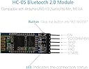
The DSD TECH HC-05 Bluetooth Serial Pass-through Module is a versatile wireless communication tool designed for Arduino enthusiasts. It features a dual-functionality Bluetooth module that operates in both master and slave modes, ensuring seamless connectivity with a variety of devices. With a compact design, user-friendly setup, and customizable settings, this module is perfect for innovative projects that require reliable wireless communication.
| ASIN | B01G9KSAF6 |
| Best Sellers Rank | #57 in Bluetooth Network Adapters |
| Brand | DSD TECH |
| Color | multicolor |
| Compatible Devices | Smartphone, Tablet |
| Customer Reviews | 4.2 out of 5 stars 840 Reviews |
| Data Link Protocol | Bluetooth |
| Data Transfer Rate | 1382400 Bits Per Second |
| Hardware Interface | Bluetooth |
| Item Dimensions L x W x H | 1.1"L x 0.6"W x 0.1"H |
| Item Weight | 0.02 Pounds |
| Manufacturer | DSD TECH |
| Mfr Part Number | sh-hc-05-us |
| Minimum Required Operating System Version | Android 2.3 Gingerbread |
| Model Number | HC-05 |
| Product Dimensions | 1.1"L x 0.6"W x 0.1"H |
| Warranty Description | 1 year warranty |
R**H
A Perfect Addition for Controlling Your Micro-Processors with Your Smartphone VIA Bluetooth Communication
Worked Perfectly. This board is a Perfect Companion to the Arduino Family of Micro Processors, and Easily Connects. Allowing one to use their Smartphone to Communicate and Control their Processor of choice. I had No Difficulty in getting the device to work, and although you can change the "Default" Settings, I found that they were suitable for my projects. I am using this particular unit with an Arduino Nano in an "Otto" Robot that I have assembled. And I am using my Cellphone to send commands to My Otto Robot, that really increased the function. The HC-06 Device was Delivered in an AntiStatic Bag and was carefully packaged for shipping. The unit arrived in Brand New Condition without any damage or bent Pins. I was more than pleasantly surprised at the Quality of the Product and the build of the Circuit Board and Attachment of the Chips. A few Connections and the Board Powered up with the Indicating LED's giving firm indication of Operation. DSD Tech did a fine job in delivery and shipping. And the Product was "As" Described. I will Buy Again from them.
M**E
Not for beginners
I choose DSD Tech, based on reviews. The product was delivered via USPS, with instructions, inside a padded envelope, inside an Amazon shipping envelope. The HC-05 module has a plastic protective cover. Module worked straight out-of-the "box", but only because I studied several examples prior to beginning. I can see why a person might give up. Testing: The module successfully RECEIVED message . Using Android phone as transmitter and the HC-05 module as receiver, the module was able to receive messages at a distance (of at least) ~15m outdoors, line of sight (15 m was max distance tested). I did not test message transmission. I will buy again (so that I can test transmission).
P**K
They are wise enough to stay with firmware version 2.0-20100601.
You can get HC-05 from a variety of vendors, some at significant discounts, but they typically are flashed with newer firmware versions that are not as robust and proven as the one shipped by DSD-Tech. I recently picked up four HC-05s from another vendor for roughly the same prices as one from DSD-Tech; Connection problems, pairings disappearing, and device crashes on data transfers. I finally bit the bullet, replaced the devices with DSD-Tech modules, and now the system runs flawlessly. No other changes, just changed the HC-05.
A**R
Buyer beware: does not have AT mode button as shown in photo
Just ordered these last week. You'll notice that only four pins have headers, and that there is no button to put the unit in AT mode. Yeah, it's fixable easy enough for someone who knows electronics, but probably not for the rookie hobbyist. Buyer beware: the photo is misleading... if you want AT mode you'll have to buy some micro switches and solder one on (the enable pin is not as big a deal IMO).
T**.
Hard to get going but great once done!
I was able to set up a remote serial link successfully after several days of learning/experimenting. I am documenting my solution so that others can benefit. It was frustrating but eventually worked very well. I purchased two of these DSD HC-05 units to set a remote serial link between my robot car and my laptop. These units cannot connect to iPhone per seller description and I can confirm it. I could not get my windows 11 laptop to reliably connect to these either. Using "advanced discovery" I could see the devices but pairing fails almost immediately. Not sure if this is an issue with my laptop or with the devices. I had to buy a 2nd unit in order to have the two talk to each other. One HC-05 is now connected to my laptop through Arduino Uno and the other will be connected to my Robot car. Here is the process I finally came up with. If your laptop connects to the HC-05 then I suppose you could manage with one Uno/HC05 pair. Need to set up one HC-05 to act as master and set a few AT parameters. The second HC-05 operates as slave (default HC-05 mode) but we need to get it's address. Have to get the devices into AT mode to get these steps done. To enter AT mode: Connections between HC-05 and Uno R3: HC-05 Pins (left) -> Uno R3 Pins (Right) GND->GND, VCC->5V, EN->3.3V, Rx->Rx, Tx->Tx. HC-05 State Pin left Open HC-05 gets power from Uno R3 and Uno R3 gets power from Laptop USB CAUTION: You should use a resistor divider any time a signal goes in to HC-05 Rx. Don't need one for Tx. Search the web. I used 1K and 2K resistors. I omit that here for simplicity in explaining but I am using one and highly recommend you use it. Connect USB from Uno to Laptop, fire up Arduino IDE on laptop, set IDE baud rate to 38400 with both "NL & CR" option selected. Select board and COM Port on IDE. Load the "null sketch" on to the Uno R3 from Arduino IDE. Null sketch: Setup and loop declarations with no code - Arduino IDE "new sketch". Do NOT add any code. Type AT hit enter then repeat in the IDE monitor input window [responses show up in the output part of the window below the input line] First AT will give you an Error response, ignore, do it again and you should see OK - means you are in AT mode. If HC-05 is in AT mode you will see the Red onboard LED slow flashing. I used the following commands to get address of the Slave before I did anything with the Master Slave HC-05 AT commands: AT+ROLE? should see +ROLE:0 which is Slave AT+ADDR? should see +ADDR:xx:xx:xxxxx [note this down, in some cases there many be fewer digits fill in 0's in front for that section]Label this HC-05 as Slave [i just used some tape to write on] Disconnect USB from Uno, disconnect Slave HC-05 from Uno Connect Master HC-05 to Uno exactly as above then follow all same steps except use the following AT commands: Master HC-05 AT commands: AT+ROLE? should see +ROLE:0 AT+ROLE=1 should see +ROLE:1 OK which is now set as master AT+CMODE=1 should see +CMOD:1 OK which now limits HC-05 Master to connect to only 1 specified address AT+BIND=xx,xx,xxxxx should see +BIND:xx,xx,xxxxx OK [Need exactly number of digits as shown, replace ":" from above with "," fill in any missing digits as preceeding 0's Label the HC-05 as Master Now we need to set up the HC-05 and Uno R3's for normal operation (no longer AT mode). Remove the EN->3.3V and leave it open Connect the two HC-05 to their respective Uno R3's, leave EN open, remove HC-05 Rx, Tx for now. Same for both Master and Slave. If you power up the two Uno R3's along with the HC-05's you should see the onboard red LED flashing in unison - this means the two have paired up. Write sketches for master and slave [I am including my sample sketches below] Leave the HC-05 Rx and Tx disconnected while you upload the sketches for master and slave. The sketches will NOT load if Uno Rx and Tx pins used for anything else. AFTER sketches are uploaded - connect both Master and Slave Rx and Tx to their respective Uno R3's. But this time they are SWAPPED on both Master and Slave. Rx->Tx and Tx->Rx. Recall the CAUTION re using the voltage divider. Rest is same as before except EN is open. This worked for me ... hope it helps you. The weblinks provided in the included documentation are hard to reach. Some of the specific links provided worked but others did not. I docked a star for that. Without that I would give them 5 stars. Hard to start up but once it works it's great! The devices are well made, especially, like the protective plastic covers. Sketches used in the review: [note: during operational mode to connect to laptop to master Uno/HC-05 while it's acting as master, I had to use Software Serial in the master. Beyond scope of this review but not hard if have the basic code below working] // null sketch void setup() { } void loop() { } // end null sketch // Uno_HC05_Master_LED.ino // HC-05 Master turns on External LED & writes to HC-05 Slave to turn on remote LED // Note HC-05 Rx to Uno Tx via resistor divider, HC-05 Tx to Uno Rx directly #define ledPin 9 // External LED on Master Uno D9 with 220 or 330 ohm resistor #define RemoteLEDon '1' #define RemoteLEDoff '0' void setup() { Serial.begin(38400); pinMode(ledPin,OUTPUT); digitalWrite(ledPin,HIGH); // turn on external LED at Master for 2 seconds to indicate successful start up delay(2000); digitalWrite(ledPin,LOW); } // end setup void loop() { Serial.write(RemoteLEDon); // Write to Slave to turn remote LED ON digitalWrite(ledPin,HIGH); // turn on local external LED at master delay(100); Serial.write(RemoteLEDoff); // Write to Slave to turn remote LED OFF digitalWrite(ledPin,LOW); // turn off local external LED at master delay(100); } // end main loop // Uno_HC05_Slave_LED.ino // HC-05 Slave to read serial input from HC-5 Master to turn on LED // Note HC-05 Rx to Uno Tx via resistor divider, HC-05 Tx to Uno Rx directly #define ledPin 9 // External LED on Slave Uno D9 with 220 or 330 ohm resistor int BTdata = 0; #define SlaveLEDon '1' #define SlaveLEDoff '0' void setup() { pinMode(ledPin,OUTPUT); Serial.begin (38400); // default rate digitalWrite(ledPin,HIGH); // turn on external LED at Slave for 2 seconds to indicate successful start up delay(2000); digitalWrite(ledPin,LOW); } // end setup void loop() { if (Serial.available()) { BTdata=Serial.read(); if(BTdata==SlaveLEDon) digitalWrite(ledPin,HIGH); else if (BTdata==SlaveLEDoff) digitalWrite(ledPin,LOW); } // end if delay(20); } // end main loop
A**S
Good product
Came in with the manual and it works, haven’t done anything else with it yet after testing it for functional use.
M**L
Obsolete!
This does NOT work with modern versions of Windows 10. It seems to need SPP 1.1 which is no longer supported by the current Bluetooth stack. Too bad, because this was very useful component. Maybe it still works under other OS's?
M**7
Works at 3.3V
The documentation is a bit inconsistent, but this did work for me at 3.3V. I'm using a Sparkfun CH340 USB to UART to test it. That outputs 3.3V at up to 600mA. The manual says the HC-05 will work at 3.1V to 4.2V at 30mA to 40mA. Amazon and DSD Tech's websites as well as the board itself all say 3.6V to 6.0V. I used two serial terminals, one set on the CH340's COM port, and one set on one of the two (why two?) HC-05 bluetooth COM ports (both on 9600 8N1) and they had no problem communicating. I got it in AT mode the first attempt using method 2, I held down the button while powering it on. I held it for a few more seconds until the light started blinking. I set their Bluetooth Tools software to 38400 (the default for method 2) and selected the CH340's COM port and I was able to change the HC-05's settings.
E**Z
Excelente
Gracias, excelente servicio
O**R
Vraiment ravi !
Cela va faire 3 fois que je tente d'acheter des modules sur des sites chinois qui commercialisent ce genre de module pour 2 à 3 fois moins cher. A chaque fois les modules ne fonctionnent pas => C'est la poubelle et 1 mois d'attente pour rien. J'ai tout essayé HM-10, HC-05, HC-06... Rien ne marche chez eux. Là je suis vraiment ravis. Les modules fonctionnent à merveille. Un peu cher, certes. Mais ils fonctionnent vraiment bien et le petit étui rigide est un vrai plus.
M**O
Dispositivo Bluetooth perfetto per Arduino
Ottimo dispositivo Bluetooth per Arduino in contenitore plastificato trasparente. Facile da utilizzare e da configurare. Funziona sia come master che come slave ( HC-05 ).
M**N
Good delivery, working product great tech support
Hi, I bought two of these to allow me to communicate between 2 arduinos. I had googled a little and it seemed simple enough from the examples I had seen, but once I got the chips I discovered none of the examples I found on-line worked. That's where the support desk from DSD came in, these guys were great, I explained what I wanted to do and they helped me every step of the way, I'm not sure I would have gotten them working without the support desk's help. So if anyone wants to send data between two arduinos using these blue tooth chips here are the steps I followed Step 1 To wire up the blue tooth to the arduinos follow the instructions on the following site, I also found arduino libraries help which controlled the serial communication ( I could not get the normal Tx Rx pins to work) http://www.martyncurrey.com/arduino-to-arduino-by-bluetooth/ However the bluetooth commands listed on this site did not work for me, that is where DSD came to my rescue. Step 2 To enter the AT command mode (where you define setting on the chip) press the button on the right hand side of the chip just above the pin as you are powering the chip on, if the chip enters command mode the led will flash slowly. Step 3 Once in command mode select one chip to be the slave and one to be master AT+ROLE=0 (Slave mode) AT+ROLE=1 (Master mode) Step 4 Set names for both chips AT+NAME= name AT+NAME? should give you the name back but didn't work for me, so instead I confirmed the name using an android phone ( note devices in master mode will not show up in a scan) Step 5 Set password The default is 1234 and you could leave it at that if you really want but probably better to change it AT+PSWD=password AT+PSWD? will return the password Make sure to set the same password on both devices Step 6 find device address AT+ADDR? Record the value for both master and slave Step 7 on both devices do the following AT+CMODE=0 and on the master AT+BIND = slave address on the slave AT+BIND = master address Step 8 both cycle both devices do not press the button to put them in command mode They should now connect to each other the led will start to flash rapidly this is them in pairing mode and once they pair the led will do a double flash once every couple of seconds. On final thing I had to set the BTserial on the arduinos to 38400 not 9600. So that's it, the delivery time was good, the chips work and the helpdesk coudn't have been better, I would buy more stuff from DSD.
J**T
Funciona como se esperaba
Buen producto. Funciuona adcecuadamente. Está protegido por una carcasa de plastico para evitar deaños en caso de caida.
Trustpilot
1 month ago
1 day ago